Reference
I2C 为什么要用开漏输出,而不能用推挽输出。
- 防止短路。两个 push pull 输出相连,如果一个输出高,一个输出低,会短路。
- 线与。开漏输出有一个输出端输出低,则整条线都为低,所有输出高才为高。
https://www.zhihu.com/question/534999506
https://www.eet-china.com/mp/a87499.html
以上都是针对 multiple masters 多个输出端的,如果是 single master config 的话,推挽输出是否可以?
2 I2C-bus features
- Only two bus lines are required; a serial data line (SDA) and a serial clock line (SCL).
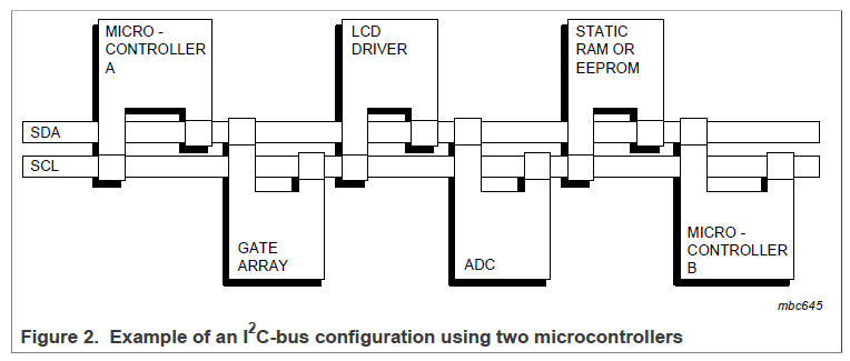
- It is a true multi-controller bus including collision detection and arbitration to prevent data corruption if two or more controllers simultaneously initiate data transfer.
- Serial, 8-bit oriented, bidirectional data transfers can be made at up to 100 kbit/s in the Standard-mode, up to 400 kbit/s in the Fast-mode, up to 1 Mbit/s in Fast-mode Plus, or up to 3.4 Mbit/s in the High-speed mode.
- Serial, 8-bit oriented, unidirectional data transfers up to 5 Mbit/s in Ultra Fast-mode
3 The I2C-bus protocol
3.1 Standard-mode, Fast-mode and Fast-mode Plus I2C-bus protocols
Each device is recognized by a unique address and can operate as either a transmitter or receiver, depending on the function of the device.
3.1.1 SDA and SCL signals
开漏或者开集输出来实现线与的功能, 即一个 controller 把 bus 拉低, bus 就呈现低电平状态。
3.1.2 SDA and SCL logic levels
\(V_{IL}=0.3V_{DD}\)
\(V_{IH}=0.7V_{DD}\)
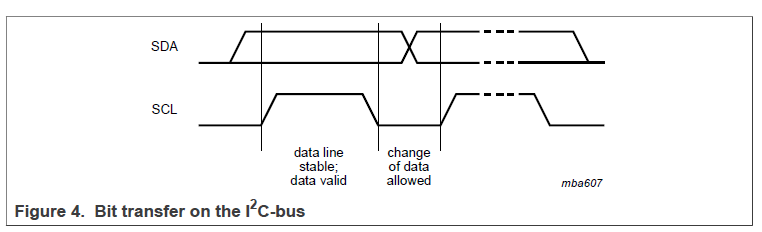
3.1.3 Data validity
SCL HIGH,SDA stable
SCL LOW,SDA change
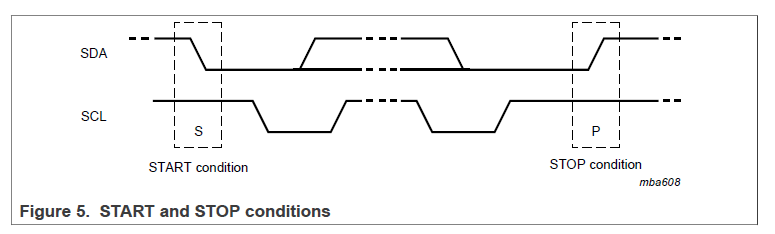
3.1.4 START and STOP conditions
START 和 STOP 都是由 controller 产生的。
- A HIGH to LOW transition on the SDA line while SCL is HIGH defines a START condition.
- A LOW to HIGH transition on the SDA line while SCL is HIGH defines a STOP condition.
3.1.5 Byte format
8bits 接一个 Ack。
MSB 传输。
如果 target 需要处理其他事情比如中断,target 可以把 SCL 拉低,让 controller 进入 wait state。
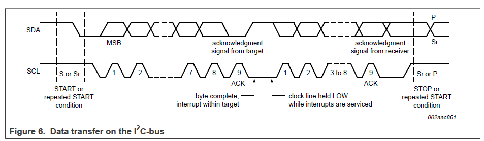
3.1.6 Acknowledge (ACK) and Not Acknowledge (NACK)
第九个 bit 低电平表示 ACK,高电平表示 NACK。
产生 NACK 的原因有:
- controller 发送的目标 address 没有 receiver 应答。
- receiver 在处理 real-time function,比如中断等,没来得及应答。
- receiver 收到了不能理解的 data or command。
- receiver 不能再收 data 了。
3.1.7 Clock synchronization
Single controller system 不用考虑。
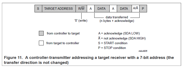
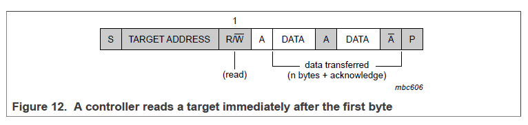
3.1.10 Target address and R/W bit
START 信号后会跟 7bits 地址, 第 8 bit 为 R/W, 0->write, 1->read。